I am indepted to Bob Herrendeen for this excellent presentation.
A common problem found in R390s is non tunable or non functional BFO adjustment.
This problem was apparent on the unit I have just begun to restore. (S/N
61).
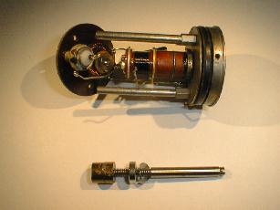
The variable oscillator is controlled by a variable inductance housed
in sealed can located in the IF module. It is connected to the front panel
through a clamped shaft and later a bellows link to the sealed module.
To center the BFO frequency to the 455 IF frequency, one must rotate
the external shaft until it is zero beat, and then set the knob to center.
If there is no end stop on the shaft, or one continues to rotate the shaft
beyond the end point pressure washer, then the threaded shaft attempts
to pull out of the core, crushing the core against the bottom of the internal
shaft bushing. I also noticed that the threads are backwards from standard
rotation, which can be confusing if you think you are actually screwing
the core into the coil.
After opening the unit, it becomes obvious what the problem is when
the core pieces fall out of the coil!
At first, I thought that it would be impossible to find a replacement.
I later was able to purchase one from Fair Radio, but had already decided
to attempt to repair the core since the core section that does most of
the tuning was still intact. The section that was broken was the 30% that
held the threaded shaft in place.
It is possible to fit the core back together and with compression,
align the segmented boundaries. Having done this, I decided to assemble
the four broken sections of the core into a half section, using a 3-minute
epoxy designed to bond metallics. (Hardman Adhesive 04001). This was done
on top of a flat surface of silicone rubber since the epoxy excess would
not stick to the surface and I could get good surface flatness on the top
of the core. Great care must be taken not to get excess epoxy onto the
area to be bonded to the remaining half because when cured, this will interfere
with the alignment of the mating surfaces. Excess epoxy on the outside
can be scrapped off with a razor blade and polished with emery cloth. The
short 3 minute cure time was chosen so the I could easily hold the pieces
in compression. The final step was to epoxy the two halves, taking care
not to get excess epoxy in the center where the shaft must seat. All this
work must be done with the aid of some magnification.
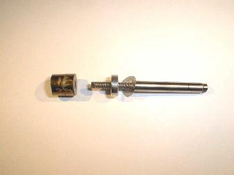
can be seen from the picture, the threaded shaft must be inserted into
the base of the coil prior to assembly onto the core. In addition, the
flex washer and support plate must also be inserted prior to the core attachment.
Prior to the final assembly the coil form was thoroughly cleaned and the
threaded shaft was lubricated after being inserted so as to avoid contamination
of the end to be epoxied into the core. In addition, since threaded shaft
appeared to be cast onto the core, I thought it was important to orient
the end of the shaft onto the core exactly as it was molded. This maintains
good concentricity as the core moves up and down inside the coil form.
Therefore, I marked the external shaft with a piece of masking tape that
aligned with a mark on the core, before sliding the core down onto the
shaft inside the coil. One only gets one shot at this, since the repaired
core was to be epoxied onto the end of the shaft while inside the coil.
By mating the core center with the correct orientation of the threaded
shaft, it was somewhat self-aligning. (I tried all this without epoxy first.).
After assembly and cure, I measured the resonant frequency of the new
coil assembly.
The repaired assembly resonance ranged from 443.274 to 462.130 kHz,
while the replacement assembly measured 449.522-480.925 kHz. I believe
that the difference is partly due to the fact that the repaired core sits
slightly higher on the threaded shaft and therefore extends deeper into
the coil at one extreme, and not as far out at the other extreme. I also
noted that the replacement coil was a model 70J1, while the repaired coil
was a model 70J3. The 70J1 had a longer shaft and somewhat different internal
component placement. The circuit was the same, but had a different parallel
capacitor value than the 70J3 and the schematic.
If I had a chance to do it again I would try to assemble the core in
one activity with an epoxy that had a somewhat longer work time. That way
I think a more precise fit of the pieces could be obtained
